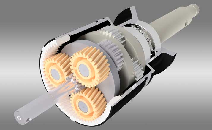


Planetary Gears GSF
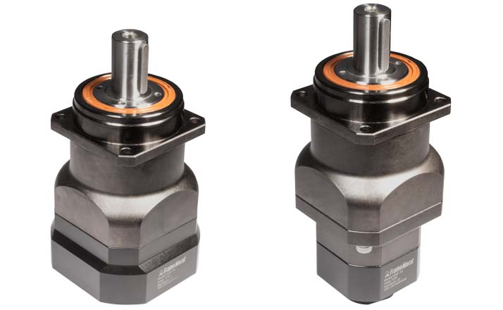
The precision planetary gear units of the GSF series with ground helical gearing and preloaded double taper roller bearings ensure low-noise synchronism due to their immense load carrying capacity and rigidity even under high load conditions. The one-piece planet carrier and the integrated needle roller bearings enable the transmission of high torques. The additional shaft sealing ring ensures maximum protection against dust and splash water in accordance with protection class IP65.
Definition of serial numbers
| Internal Group No. |
Type | 大小 | Backlash level | Input hollow shaft | Ratio | ||||
| 3 | – | GSF | 090 | – | 1 | – | 19 | – | 005 |
Backlash level: 1 = Standard; 0 = Reduced backlash
Input hollow shaft diam. = Max. motorshaft diam. = D9 in gearbox dimensions
Dimensions

| Stage | GSF062 | GSF075 | GSF100 | GSF142 | GSF180 | |||
| Centering diameter output | D2 | g6 | 60 | 70 | 90 | 130 | 160 | |
| Output shaft diameter | D4 | k6 | 16 | 22 | 32 | 40 | 55 | |
| Shaft height including feather key | D5 | 18 | 24,5 | 35 | 43 | 59 | ||
| Hole circle diameter output | D6 | 68 | 85 | 120 | 165 | 215 | ||
| Clamping system diameter | D8 | 1 | 40 | 49 | 67 | 80 | 107 | |
| 2 | 27 | 40 | 49 | 67 | 80 | |||
| Max. motor shaft diameter | D9 | F7 | 1 | 19 | 24 | 28 | 38 | 55 |
| 2 | 11 | 19 | 24 | 28 | 35 | |||
| Hole circle diameter input | D10 | 1 | 60,5 | 90 | 120 | 145 | 186 | |
| 2 | 42 | 60,5 | 90 | 120 | 145 | |||
| 住房的長度 | L1 | 1 | 78 | 108,5 | 119 | 158,5 | 202,5 | |
| 2 | 100 | 129,3 | 163,5 | 196,5 | 247,5 | |||
| Shaft length output | L2 | 48 | 56 | 88 | 112 | 112 | ||
| Shaft length from shoulder | L3 | 28 | 36 | 58 | 82 | 82 | ||
| Centering depth output | L4 | 18 | 18 | 27 | 27 | 26 | ||
| Distance from shaft end | L5 | 4 | 2 | 4 | 4 | 6 | ||
| Feather key length | L6 | 20 | 32 | 50 | 70 | 70 | ||
| Max. input length motor shaft | L7 | 1 | 35,5 | 50 | 57 | 74,5 | 105 | |
| 2 | 21 | 35,5 | 50 | 57 | 74,5 | |||
| Distance to center of screw | L8 | 1 | 6 | 7 | 9 | 10,5 | 11 | |
| 2 | 4,5 | 6 | 7 | 9 | 10,5 | |||
| Flange thickness output | L11 | 6 | 7 | 10 | 12 | 15 | ||
| Distance clamping ring – housing | L13 | 1 | 15、5 | 17,5 | 25,5 | 25,5 | 34 | |
| 2 | 11 | 15、5 | 17,5 | 25,5 | 25,5 | |||
| Square housing output | SQ1 | 62 | 76 | 106 | 142 | 180 | ||
| Square housing input | SQ2 | 1 | 62 | 90 | 120 | 142 | 180 | |
| 2 | 44 | 62 | 90 | 120 | 142 | |||
| Feather key width | B1 | h9 | 5 | 6 | 10 | 12 | 16 | |
| Min. mounting thread x depth | G2 | 4 x | 1 | M5 x 8 | M6 x 10 | M8 x 13 | M10 x 16 | M12 x 20 |
| 2 | M4 x 6 | M5 x 8 | M6 x 10 | M8 x 13 | M10 x 16 | |||
| Min. mounting thread x depth | G3 | M5 x 8 | M8 x 13 | M10 x 16 | M12 x 20 | M14 x 22 | ||
| Hole bore | H1 | 4 x | 5,5 | 6,8 | 9 | 11 | 13 | |
| Angle in ° | W1 | 45 | 45 | 45 | 45 | 45 | ||
| x times angle in ° | W2 | 4 x 90 | 4 x 90 | 4 x 90 | 4 x 90 | 4 x 90 | ||
| Angle in ° | W3 | 30 | 30 | 30 | 30 | 30 | ||
| x times angle in ° | W4 | 4 x 90 | 4 x 90 | 4 x 90 | 4 x 90 | 4 x 90 |
Find additional info tomotor flangesandreduction sleevesbelow.
Power table
| Leistungsdaten | GSF062 | GSF075 | GSF100 | GSF142 | GSF180 | Stage | |||
| Service lifetime*1 | tL | h | 30000 | ||||||
| Nominal input speed | n1 | rpm | 4000 | 4000 | 4000 | 4000 | 3000 | ||
| Max. input speed | n1max. | rpm | 8000 | 8000 | 8000 | 8000 | 6000 | ||
| Standard backlash | jt | arcmin | <= 3 | 1 | |||||
| <= 5 | 2 | ||||||||
| Noise level*2 | Qg | dB (A) | <= 58 | <= 60 | <= 63 | <= 65 | <= 67 | ||
| Efficiency | ƞ | % | >= 97 | 1 | |||||
| >= 94 | 2 | ||||||||
| Protection class | IP65 | ||||||||
| Torsional rigidity | ct | Nm/arcmin | 8 | 15 | 27 | 60 | 150 | ||
| Max. radial force*3 | F2r | N | 2400 | 4300 | 8800 | 13000 | 17900 | ||
| Max. axial force*3 | F2a | N | 1950 | 3850 | 7600 | 10950 | 15200 | ||
| Operating temperature | TB | °C | -25°C – +90°C | ||||||
| Lubrication | Synthetic grease (lifetime-lubricated) | ||||||||
| Weight with flange*4 | mg | kg | 1,70 | 4,50 | 8,30 | 16,70 | 34,30 | 1 | |
| 2,52 | 4,80 | 8,48 | 19,98 | 37,30 | 2 | ||||
| Mounting position | Any | ||||||||
| Output torques | GSF062 | GSF075 | GSF100 | GSF142 | GSF180 | Ratio | Stage | ||
| Nominal output torque*5 | T2N | Nm | 62 | 173 | 227 | 656 | 1266 | 3 | 1 |
| 54 | 153 | 218 | 538 | 1122 | 4 | 1 | |||
| 50 | 163 | 350 | 649 | 1248 | 5 | 1 | |||
| 47 | 149 | 324 | 602 | 1163 | 7 | 1 | |||
| 45 | 143 | 309 | 576 | 1112 | 10 | 1 | |||
| 62 | 149 | 313 | 656 | 1266 | 15 | 2 | |||
| 54 | 132 | 280 | 583 | 1122 | 20 | 2 | |||
| 50 | 166 | 311 | 649 | 1248 | 25 | 2 | |||
| 47 | 137 | 292 | 612 | 1174 | 30 | 2 | |||
| 47 | 134 | 289 | 602 | 1163 | 35 | 2 | |||
| 45 | 129 | 278 | 581 | 1124 | 40 | 2 | |||
| 50 | 145 | 311 | 649 | 1248 | 50 | 2 | |||
| 47 | 134 | 289 | 602 | 1163 | 70 | 2 | |||
| 45 | 127 | 275 | 576 | 1112 | 100 | 2 | |||
| Max. acceleration torque*6 | T2B | Nm | 112 | 311 | 409 | 1181 | 2279 | 3 | 1 |
| 97 | 275 | 392 | 1049 | 2020 | 4 | 1 | |||
| 90 | 293 | 630 | 1168 | 2246 | 5 | 1 | |||
| 85 | 268 | 583 | 1084 | 2093 | 7 | 1 | |||
| 81 | 257 | 556 | 1037 | 2002 | 10 | 1 | |||
| 112 | 268 | 563 | 1181 | 2279 | 15 | 2 | |||
| 97 | 238 | 504 | 1049 | 2020 | 20 | 2 | |||
| 90 | 299 | 560 | 1168 | 2246 | 25 | 2 | |||
| 85 | 247 | 526 | 1102 | 2113 | 30 | 2 | |||
| 85 | 241 | 520 | 1084 | 2093 | 35 | 2 | |||
| 81 | 232 | 500 | 1046 | 2023 | 40 | 2 | |||
| 90 | 261 | 560 | 1168 | 2246 | 50 | 2 | |||
| 85 | 241 | 520 | 1084 | 2093 | 70 | 2 | |||
| 81 | 229 | 495 | 1037 | 2002 | 100 | 2 | |||
| Emergency stop torque*7 | T2Not | Nm | 186 | 519 | 681 | 1968 | 3798 | 3 | 1 |
| 162 | 459 | 654 | 1749 | 3366 | 4 | 1 | |||
| 150 | 489 | 1050 | 1947 | 3744 | 5 | 1 | |||
| 141 | 447 | 972 | 1806 | 3489 | 7 | 1 | |||
| 135 | 429 | 927 | 1728 | 3336 | 10 | 1 | |||
| 186 | 447 | 939 | 1968 | 3798 | 15 | 2 | |||
| 162 | 396 | 840 | 1749 | 3366 | 20 | 2 | |||
| 150 | 498 | 933 | 1947 | 3744 | 25 | 2 | |||
| 141 | 411 | 876 | 1836 | 3522 | 30 | 2 | |||
| 141 | 402 | 867 | 1806 | 3489 | 35 | 2 | |||
| 135 | 387 | 834 | 1743 | 3372 | 40 | 2 | |||
| 150 | 435 | 933 | 1947 | 3744 | 50 | 2 | |||
| 141 | 402 | 867 | 1806 | 3489 | 70 | 2 | |||
| 135 | 381 | 325 | 1728 | 3336 | 100 | 2 | |||
| Mass moment of inertia | GSF062 | GSF075 | GSF100 | GSF142 | GSF180 | Ratio | Stage | ||
| Mass moment of inertia*8 | J1 | kgcm2 | 0,15 | 0,60 | 3,21 | 9,18 | 28,82 | 3 | 1 |
| 0,14 | 0,51 | 2,80 | 7,51 | 23,56 | 4 | 1 | |||
| 0,13 | 0,45 | 2,71 | 7日,40 | 23,74 | 5 | 1 | |||
| 0,13 | 0,42 | 2,54 | 7,15 | 22,40 | 7 | 1 | |||
| 0,12 | 0,42 | 2,51 | 7,01 | 22,35 | 10 | 1 | |||
| 0,03 | 0,13 | 0,47 | 2,63 | 7,30 | 15 | 2 | |||
| 0,03 | 0,13 | 0,47 | 2,63 | 7,30 | 20 | 2 | |||
| 0,03 | 0,13 | 0,47 | 2,43 | 7,10 | 25 | 2 | |||
| 0,03 | 0,13 | 0,47 | 2,43 | 7,10 | 30 | 2 | |||
| 0,03 | 0,13 | 0,47 | 2,43 | 7,10 | 35 | 2 | |||
| 0,03 | 0,13 | 0,47 | 2,43 | 6,92 | 40 | 2 | |||
| 0,03 | 0,13 | 0,44 | 2,43 | 6,92 | 50 | 2 | |||
| 0,03 | 0,13 | 0,44 | 2,39 | 6,72 | 70 | 2 | |||
| 0,03 | 0,13 | 0,44 | 2,39 | 6,72 | 100 | 2 | |||
*1 Load factor KA=1, n2=100 rpm ,at room temperature T=20°C in new condition
*2 Sound pressure level at 1m distance, measured for an input speed of 3000 rpm without load
*3 On the center of the output shaft
*4 Deviation of up to 10 % possible
* 5使用壽命:30000 h, n2=100 rpm
*6 Max 1000 cycles per hour. Acceleration torque proportion < 5% of the total operation time
*7 Max 1000 cycles over the gear service life
*8 Related to the input shaft
Motorflanges


-
GSF 62
Gearbox type Centering diameter
ZHole circle
LKMax. centering depth
LZMax. motor shaft length
LScrew type
BArticle number GSF062 1st. 30 46 5 30 M4 3-G062-030-001 50 70 5 30 M5 3-G062-050-001 50 70 5 30 M4 3-G062-050-002 50 95 5 30 M6 3-G062-050-004 60 75 5 30 M6 3-G062-060-001 60 75 5 30 M5 3-G062-060-002 70 90 5 40 M6 3-G062-070-002 70 90 5 30 M5 3-G062-070-003 80 100 5 30 M6 3-G062-080-001 GSF062 2st. 30 46 4 25 M4 3-G044-030-001 40 63 4 25 M4 3-G044-040-002 50 70 3 25 M5 3-G044-050-002 50 70 3 30 M4 3-G044-050-004 60 75 4 25 M5 3-G044-060-001 -
GSF 75
Gearbox type Centering diameter
ZHole circle
LKMax. centering depth
LZMax. motor shaft length
LScrew type
BArticle number GSF075 1st. 70 90 8 50 M6 3-G090-070-001 70 90 8 50 M5 3-G090-070-002 80 100 8 50 M6 3-G090-080-001 95 115 8 50 M8 3-G090-095-002 95 130 8 50 M8 3-G090-095-003 95 115 13 55 M8 3-G090-095-006 110 145 8 50 M8 3-G090-110-001 110 145 22 65 M8 3-G090-110-002 110 130 8 50 M8 3-G090-110-003 130 165 8 50 M10 3-G090-130-001 GSF075 2st. 30 46 5 30 M4 3-G062-030-001 50 70 5 30 M5 3-G062-050-001 50 70 5 30 M4 3-G062-050-002 50 95 5 30 M6 3-G062-050-004 60 75 5 30 M6 3-G062-060-001 60 75 5 30 M5 3-G062-060-002 70 90 5 40 M6 3-G062-070-002 70 90 5 30 M5 3-G062-070-003 80 100 5 30 M6 3-G062-080-001 -
GSF 100
Gearbox type Centering diameter
ZHole circle
LKMax. centering depth
LZMax. motor shaft length
LScrew type
BArticle number GSF100 1st. 70 90 9 63 M6 3-G120-070-001 95 115 9 63 M8 3-G120-095-002 110 145 9 63 M8 3-G120-110-001 110 130 9 63 M8 3-G120-110-003 110 165 9 63 M10 3-G120-110-005 130 165 9 63 M10 3-G120-130-001 GSF100 2st. 70 90 8 50 M6 3-G090-070-001 70 90 8 50 M5 3-G090-070-002 80 100 8 50 M6 3-G090-080-001 95 115 8 50 M8 3-G090-095-002 95 130 8 50 M8 3-G090-095-003 95 115 13 55 M8 3-G090-095-006 110 145 8 50 M8 3-G090-110-001 110 145 22 65 M8 3-G090-110-002 110 130 8 50 M8 3-G090-110-003 130 165 8 50 M10 3-G090-130-001 -
GSF 142
Gearbox type Centering diameter
ZHole circle
LKMax. centering depth
LZMax. motor shaft length
LScrew type
BArticle number GSF142 1st. 114,3 200 8 80 M12 3-G142-114-001 180 215 8 80 M12 3-G142-180-001 200 235 8 80 M12 3-G142-200-001 GSF142 2st. 70 90 9 63 M6 3-G120-070-001 95 115 9 63 M8 3-G120-095-002 110 145 9 63 M8 3-G120-110-001 110 130 9 63 M8 3-G120-110-003 110 165 9 63 M10 3-G120-110-005 130 165 9 63 M10 3-G120-130-001 -
GSF 180
Gearbox type Centering diameter
ZHole circle
LKMax. centering depth
LZMax. motor shaft length
LScrew type
BArticle number GSF180 1st. 114,3 200 13 115 M12 3-G180-114-001 200 235 13 115 M12 3-G180-200-001 GSF180第二任丈夫。 114,3 200 8 80 M12 3-G142-114-001 180 215 8 80 M12 3-G142-180-001 200 235 8 80 M12 3-G142-200-001
Reduction sleeves


Definition of serial number for reduction sleeves
| Internal Group No. | Type | Input hollow shaft diam. D | Motor shaft diam. d | |||
| 3 | – | G | – | 035 | – | 028 |
| 3 | – | G | – | 011 | – | 009 |
| Gearbox type |
大小 | Stages | Internal diam. D |
Motor shaft diameter d in mm | ||||||||||||||||||
| 6 | 8 | 9 | 10 | 11 | 12 | 12.7 | 14 | 16 | 19 | 22 | 24 | 28 | 32 | 35 | 38 | 42 | 48 | 55 | ||||
| GSF | 62 | 1 | 19 | ✓ | ✓ | ✓ | ✓ | ✓ | ✓ | (✓) | ||||||||||||
| 2 | 11 | ✓ | ✓ | ✓ | (✓) | |||||||||||||||||
| 75 | 1 | 24 | ✓ | ✓ | ✓ | ✓ | (✓) | |||||||||||||||
| 2 | 19 | ✓ | ✓ | ✓ | ✓ | ✓ | ✓ | (✓) | ||||||||||||||
| 100 | 1 | 28 | ✓ | ✓ | ✓ | (✓) | ||||||||||||||||
| 2 | 24 | ✓ | ✓ | ✓ | ✓ | (✓) | ||||||||||||||||
| 142 | 1 | 38 | ✓ | ✓ | ||||||||||||||||||
| 2 | 28 | ✓ | ✓ | ✓ | (✓) | |||||||||||||||||
| 180 | 1 | 55 | (✓) | |||||||||||||||||||
| 2 | 35 | ✓ | ✓ | ✓ | (✓) | |||||||||||||||||
✓= Reduction sleeve available;
(✓) = no reduction sleeve necessary;
(✓)* = Possible as a specially designed model. Further diameters can also be provided. Please contact us directly.